FT-7325-C001 · Mechanical integration
Overview and files · Software integration
Start with the engineering files
Check the resource table for this exact model's dimensioned 2D drawing and STEP model. The official dimensioned image is supplied below; check the resource table for STEP availability. The outline dimensions on the overview, if present, are insufficient to release a mounting part for manufacture.
Use a dimensioned, approved drawing for tolerances and interfaces; use STEP for assembly and clearance checks. STL is suitable for visualization or fit prototypes only when its units and scale are confirmed; do not derive manufacturing tolerances from its mesh. Ask the manufacturer to resolve any drawing/CAD discrepancy.
Official dimensioned drawing
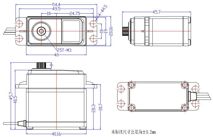
Full-size drawing · Official source
Check before designing the bracket
| Interface | Confirm from this model's documents |
|---|---|
| Envelope and datum | Units, origin, axes, housing size, projections and mounting faces |
| Mounting holes | Hole centers, diameters, threads, usable screw depth, screw length and tightening requirements |
| Output / horn / secondary shaft | Spline or shaft definition, horn compatibility, retention and protrusion |
| Joint zero and travel | Drawing zero, electrical zero, rotation direction, usable travel and hard stops |
| Cable and connector | Exit direction, mating connector, unplugging space, bend allowance and full-travel routing |
| Load and supports | Force direction, lever arm, continuous/peak torque, duty cycle, radial/axial load limits and any external bearing requirements |
Refer to the supplied drawing for dimensions; unspecified fits, tolerances and load limits still require model-specific confirmation. Model-specific horn, screw and bearing recommendations require confirmation.
Assembly verification sequence
- Record CAD/drawing revision and units. Check key dimensions against the physical sample before detailed bracket design.
- Align the housing mounting datum and output axis in the assembly; place the horn at a documented reference position.
- Check the full confirmed travel for housing/horn/bracket interference and cable tension, including assembly tolerances.
- Confirm screw engagement, tool access and service access without bottoming screws or loading the case incorrectly.
- Verify control direction and zero unloaded using the software workflow, then attach the mechanism and expand motion gradually within verified limits.
Load evaluation and handoff
Stall torque is not a continuous rating. Record the actual force direction, lever arm, acceleration, duty cycle, temperature and impact conditions. A single torque-test curve does not establish continuous, radial or axial load capacity.
Deliver the assembly revision, drawing/CAD revisions, horn/bracket part IDs, installed zero, allowed travel and marked clearance screenshots to the control developer. Return any unresolved geometry or loading questions through technical support.