First Motion
Back to the getting-started path · Bus servo setup
This page is for bus servos with a confirmed application layer and starts from communication already established: the power-up order, the PING check and recording the ID / baud rate are in Bus servo setup. The goal of this page: the motion can be stopped and the output can be switched off, and a record is kept — only then does it pass.
The first motion has one example figure per application layer: TTL / RS-485 models send a write command frame (Figure 2), Modbus-RTU models write a single register (Figure 3), and the CAN / FU series uses the UAVCAN debug tool (Figure 4; communication settings in Bus servo setup); you can also run the matching SDK's own example. A PWM servo has no communication to establish, so its first-motion check is done on the PWM servo setup page.
Safety steps
- Run the servo with no load (remove the load) and clear the motion envelope.
- Confirm that the model and ID are the servo you intend to control.
- Read the current position first; do not start by putting the target position far away from it.
- Set a low speed (only if the model supports those registers — see the series' memory table parameters).
- Offset the target position by a very small amount.
- Watch current, temperature, sound and feedback; on anything abnormal, disconnect the motor power immediately.
- Verify the way to switch the output off, then widen the motion range step by step.
Figure 1 (Safety steps · Small offset): the hollow circle is the current position and the filled circle is the target; move only a small step, leaving mechanical clearance between the target position and the travel limit.
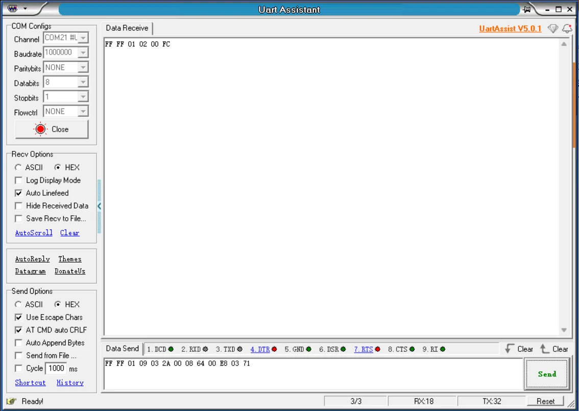
Figure 2 (TTL / RS-485 bus · Send the write command frame): open UartAssist (the same tool as in Bus servo setup).
- In COM Configs, select the correct port (COM21 in the figure), the baud rate, Paritybits NONE, Databits 8, Stopbits 1 and Flowctrl NONE — the same values used to verify the connection in Bus servo setup.
- Click "Open" — the button turns into a red "Close", meaning the port is taken; before sending, make sure the servo's motor power is connected (the serial port does not power the servo).
- In the "Data Send" area, enter the WRITE DATA frame
FF FF 01 09 03 2A 00 08 64 00 E8 03 71and click "Send". - This frame is built from the HLS memory table:
03is the write command (WRITE DATA),2Ais the start address 0x2A ("Target Position"), and the following 6 bytes are written consecutively from that address —00 08is target position 0x0800,64 00is target current 0x0064, andE8 03is running speed 0x03E8 (each 16-bit register has the low byte first), with71as the checksum; the three registers happen to be consecutive in the memory table (0x2A / 0x2C / 0x2E). For an HLS model these three registers must be written together: writing only the target position, without the target current and running speed, will not move the servo. - The "Data Receive" area shows a reply frame and the servo turns — the first motion succeeded. The
FF FF 01 02 00 FCabove the receive area is the previous page's PING reply. - The target offsets only a small step. If the model is not HLS, rewrite the addresses and data from your own model's memory table; the frame structure and checksum algorithm are in the FT-SCS Protocol.
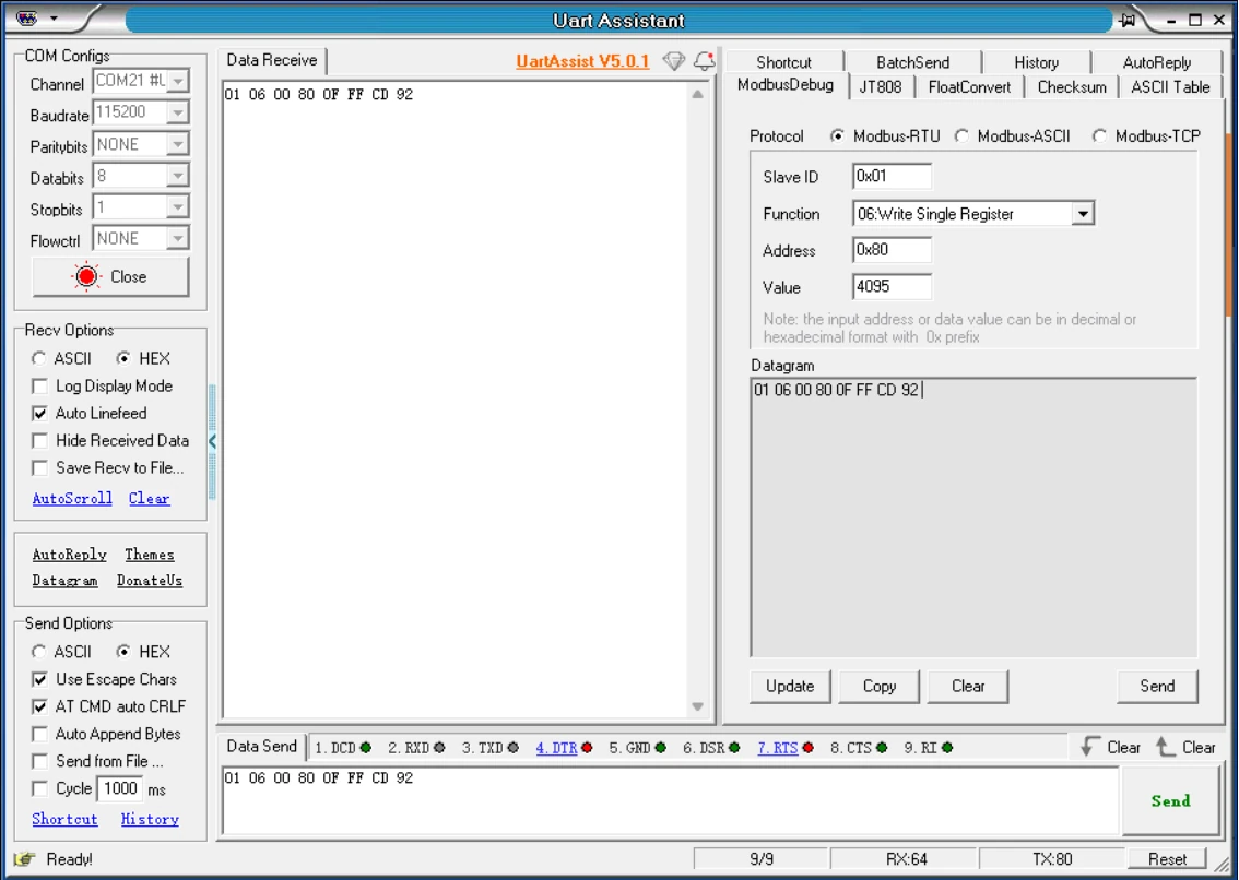
Figure 3 (Modbus-RTU · Send the write command frame): the entry to the "AutoReply" → "ModbusDebug" panel is in Bus servo setup, Figure 6 to Figure 8; here we start from filling in the panel:
- Protocol: select Modbus-RTU; Function: select 06:Write Single Register.
- Slave ID = the servo ID (0x01 in the figure, the default station number).
- Address: 0x80 — the "Target Position" of the SMSMB memory table.
- Value: the value to write — 4095 in the figure, i.e. move the servo to position 4095.
- Click "Update" — the "Datagram" area generates the hexadecimal frame
01 06 00 80 0F FF CD 92; copy it to the "Data Send" area and click "Send" — before sending, make sure the servo's motor power is connected (the serial port does not power the servo). - The "Data Receive" area shows a reply frame and the servo turns — the first motion succeeded; the reply to a 06 write of a single register is an echo of the original frame, so the receive and send areas show the same frame in the figure.
- Modbus addresses and data are big-endian (0x0080 is written
00 80, 4095 is written0F FF) — exactly the opposite of the FT-SCS frame in Figure 2; register addresses and value ranges follow the SMSMB memory table.
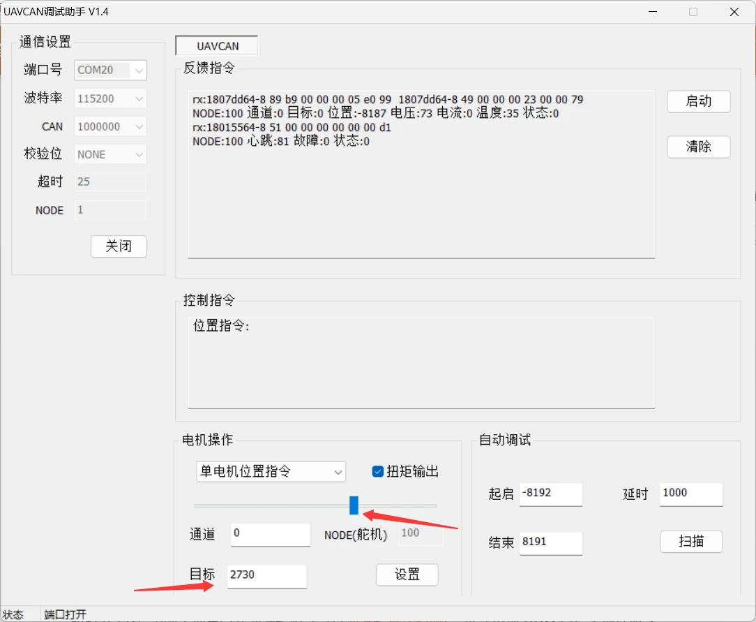
Figure 4 (CAN / FU series · Send the position command): do the first motion in the UAVCAN debug tool; communication settings are in Bus servo setup. The screenshots keep the tool's original Chinese UI, and each Chinese label below is followed by its meaning:
- In the motor operation area (电机操作), select Single motor position command (单电机位置指令), fill in the channel and NODE (servo), and keep Torque output (扭矩输出) ticked.
- Move the slider only a small amount (or enter a nearby value in Target (目标) and click Set (设置)) — the servo immediately moves to that position value.
- In the feedback area, Target (目标) is the value you asked for and Position (位置) is the value the servo reads back.
- Untick Torque output (扭矩输出) to stop driving.
- The values in the figure are examples; the model's documentation is authoritative.
Raw position is not a universal angle
Figures 2 and 3 above belong to different models and application layers — Figure 2 is FT-SCS on HLS, Figure 3 is Modbus-RTU on SMSMB; addresses, byte order and value ranges all differ, so write only from your own model's memory table and never copy between the examples (the same holds for the CAN example, Figure 4).
Series may use different position resolutions, center values, ranges and direction encodings. Position values such as 0, 512, 2048 or 4095 cannot be interpreted without the exact model's memory table; some models (such as the UAVCAN series) use signed counts, so position values can be negative. Before converting an angle into a position value, confirm:
- the valid raw position range (signed counts or not, and which end the negatives represent)
- the counts per revolution or per rated travel
- multi-turn / continuous rotation modes
- how the direction bit or signed speed is expressed
- mechanical soft limits and the zero position
Before converting, look up the register addresses, units and read/write permissions of Target Position and Current Position in the series' memory table parameters; address structures are not shared between series — do not apply one series' values directly to another model.
One common pattern (a reference only, not a general formula) — some models take a travel of 0–4095 at about 0.088 degrees per unit, i.e. 0–4095 corresponds to about 0–360° (neutral 2048 ≈ 180°). Other series use different notations, for example:
- the SCSCL series' target position is
0–1023"steps" - the UAVCAN series uses
-8192to8192(1 = 0.02197 degrees, corresponding to ±180° of the output shaft)
The exact range and unit are in the "Target Position" row of the series' memory table (memory table parameters).
Switch the output off before calibrating or setting zero
Before setting the zero/neutral position or calibrating, send a stop or output-off command so the servo is in the free state, then find the neutral by hand and write the persisted parameter; calibrating while the servo is holding force introduces an offset. The neutral/zero calibration bits and how to write them are in each series' memory table (see the memory table parameters directory) — SHC and SMSMB have a neutral-setting entry, UAVCAN a zero-calibration entry.
Records to keep afterwards
On top of the records from Bus servo setup, add: the current-position value baseline, the speed and acceleration settings, how to switch the output off and stop, the no-load result, anomalies and the date. Re-validate when switching to another model or firmware version; do not carry over this record.
Next steps
- Protocol and parameters
- SDK Overview
- FT-SCS Protocol: the frame structure and checksum algorithm of the write command — the full source of the Figure 2 frame
- Troubleshooting
- Mechanics and assembly