Servo CANopen Complete Communication Protocol
This page is a transcription of the official《舵机CANOPEN完整通信协议》(Servo CANopen Complete Communication Protocol) document. For the SHC series memory table (CANopen object dictionary), see SHC memory table.
1 CANopen network communication
CANopen is a network transport application-layer protocol based on the CAN bus, following a master-slave communication architecture. Master and slave nodes read/write dictionary data and exchange other information through the Process Data Object (PDO) and the Service Data Object (SDO). The CIA301 (DS301) protocol standard defines the basic communication framework of CANopen, and CIA402 (DS402) defines the concrete implementation and standards for drives and motion control. Through the specification and definition of these standards, motion devices and control devices from different manufacturers can be combined more easily.
2 CIA301
2.1 Communication identifier
CANopen redefines the 11-bit ID of CAN2.0A as COB-ID = function code (upper 4 bits) + node address (lower 7 bits)
COB-ID composition format
| bit 10~7 | bit 6~0 |
|---|---|
| Function code | NodeID |
COB-ID allocation table
| Communication object | Function code | Node address | COB-ID |
|---|---|---|---|
| NTM | 0000b | 0 | 0h |
| SYNC | 0001b | 0 | 80h |
| EMCY | 0001b | 1 - 127 | 80h+NodeID |
| TPDO1 | 0011b | 1 - 127 | 180h+NodeID |
| TPDO2 | 0101b | 1 - 127 | 280h+NodeID |
| TPDO3 | 0111b | 1 - 127 | 380h+NodeID |
| TPDO4 | 1001b | 1 - 127 | 480h+NodeID |
| RPDO1 | 0100b | 1 - 127 | 200h+NodeID |
| RPDO2 | 0110b | 1 - 127 | 300h+NodeID |
| RPDO3 | 1000b | 1 - 127 | 400h+NodeID |
| RPDO4 | 1010b | 1 - 127 | 500h+NodeID |
| TSDO | 1011b | 1 - 127 | 580h+NodeID |
| RSDO | 1100b | 1 - 127 | 600h+NodeID |
| Heartbeat | 1110b | 1 - 127 | 700h+NodeID |
| boot-up | 1110b | 1 - 127 | 700h+NodeID |
2.2 Network management NMT
The network management system (NMT) is used to initialize, start and stop the nodes in the network; it follows a master-slave architecture and there can only be one NMT master.
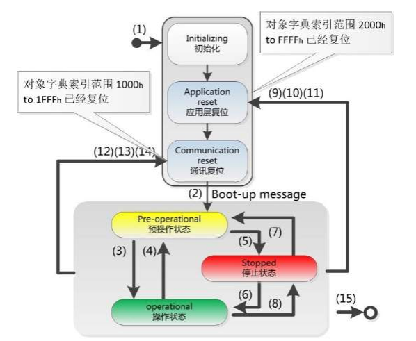
The NMT commands are as follows:
| NMT command code | Description | Allowed communication objects |
|---|---|---|
| 0x01 | Change the node state to the operational state | SDO, NMT, EMCY, heartbeat |
| 0x02 | Change the node state to the stopped state | EMCY, NMT, heartbeat |
| 0x80 | Change the node state to the pre-operational state | SDO, PDO, NMT, SYNC, EMCY, heartbeat |
| 0x81 | Reset node | The node enters the Initialization state after restarting |
| 0x82 | Reset communication | Only the communication parameters are reset; the node enters the Initialization state |
The NMT state codes are as follows:
| NMT state code | Description |
|---|---|
| 0x00 | Boot up state |
| 0x04 | Stopped state |
| 0x05 | Operational state |
| 0x7f | Pre-operational state |
NMT message
| COB-ID | Byte 0 | Byte 1 |
|---|---|---|
| 000h | NMT command | NodeID |
Note: NodeID range 1~127, 0 means broadcast instruction
2.3 Service data object SDO
SDO is mainly used for parameter configuration of the slave nodes by the CANopen master. Service confirmation is the biggest feature of SDO: a reply is generated for every message, ensuring the accuracy of data transmission. In a CANopen system, the CANopen slave node usually acts as the SDO server and the CANopen master node acts as the client (called CS communication). Through the index and sub-index, the SDO client can access the object dictionary on the SDO server. In this way the CANopen master node can access the parameters of any object dictionary entry of the slave node, and SDO can also transmit data of any length (when the data length exceeds 4 bytes it is split into multiple messages for transmission).
SDO write operation format
| Operation | COB-ID | Byte 0 | Byte 1 Byte 2 | Byte 3 | Byte 4 ~ Byte 7 |
|---|---|---|---|---|---|
| Send | 600h+NodeID | 23h | Main index | Sub-index | Data (4 bytes) |
| Send | 600h+NodeID | 27h | Main index | Sub-index | Data (3 bytes) |
| Send | 600h+NodeID | 2Bh | Main index | Sub-index | Data (2 bytes) |
| Send | 600h+NodeID | 2Fh | Main index | Sub-index | Data (1 byte) |
| Return | 580h+NodeID | 60h | Main index | Sub-index | Padded with 0 |
| Return | 580h+NodeID | 80h | Main index | Sub-index | Abort code |
SDO read operation format
| Operation | COB-ID | Byte 0 | Byte 1 Byte 2 | Byte 3 | Byte 4 ~ Byte 7 |
|---|---|---|---|---|---|
| Send | 600h+NodeID | 40h | Main index | Sub-index | Padded with 0 |
| Return | 580h+NodeID | 43h | Main index | Sub-index | Data (4 bytes) |
| Return | 580h+NodeID | 47h | Main index | Sub-index | Data (3 bytes) |
| Return | 580h+NodeID | 4Bh | Main index | Sub-index | Data (2 bytes) |
| Return | 580h+NodeID | 4Fh | Main index | Sub-index | Data (1 byte) |
| Return | 580h+NodeID | 80h | Main index | Sub-index | Abort code |
SDO abort codes
| Abort code | Description |
|---|---|
| 05 04 00 01 | Invalid or unknown SDO command specifier |
| 06 01 00 01 | Attempt to read a write-only object |
| 06 01 00 02 | Attempt to write a read-only object |
| 06 02 00 00 | Object does not exist in the object dictionary |
| 06 04 00 41 | Object cannot be mapped to a PDO |
| 06 07 00 12 | Data type mismatch |
| 06 09 00 11 | Sub-index does not exist |
| 06 09 00 30 | Value range of parameter exceeded |
| 08 00 00 24 | No data available |
2.4 Process data object PDO
PDO belongs to process data and is used for one-way transmission of real-time data, without requiring the receiving node to reply with a CAN message for confirmation; it follows the producer-consumer model. From the perspective of the slave node, PDO can be divided into RPDO and TPDO; the final transmission mode is determined jointly by the communication parameters and the mapping parameters.
RPDO/TPDO mapping object address definition:
| bit31 ~ bit16 | bit15 ~ bit8 | bit7 ~ bit0 |
|---|---|---|
| Index | Sub-index | Bit length |
PDO object list:
| Name | COB-ID | Communication object | Mapping object |
|---|---|---|---|
| RPDO1 | 200h+NodeID | 1400h | 1600h |
| RPDO2 | 300h+NodeID | 1401h | 1601h |
| RPDO3 | 400h+NodeID | 1402h | 1602h |
| RPDO4 | 500h+NodeID | 1403h | 1603h |
| TPDO1 | 180h+NodeID | 1800h | 1A00h |
| TPDO2 | 280h+NodeID | 1801h | 1A01h |
| TPDO3 | 380h+NodeID | 1802h | 1A02h |
| TPDO4 | 480h+NodeID | 1803h | 1A03h |
PDO communication parameters: the COB-ID, state bit, transmission type, inhibit time and event timer related to a PDO can all be configured through the corresponding communication object dictionary entries. PDO mapping parameters: by configuring the mapping object dictionary entry of a PDO, the actual data content carried by the PDO can be set.
2.5 Synchronization object SYNC
The synchronization object is a special mechanism used to keep sending and receiving synchronized and consistent among multiple nodes in the same network; it is mostly used for the synchronized transmission of PDOs. It can be configured through the following dictionary entries: 1006h (communication cycle period for synchronized transmission), 1007 (synchronous window length), 1005h (synchronization object).
| COB-ID | Data |
|---|---|
| 80h | None |
2.6 Emergency object service EMCY
The Emergency object is triggered when an error occurs inside the device, sending the device's internal error code to notify the NMT master. Emergency messages are diagnostic messages and generally do not affect CANopen communication. Their CAN-ID is stored in index 1014h and is generally defined as 080h+NodeID; the data contains 8 bytes.
When a node fails, the error register and the predefined error field must be updated. The emergency message content follows the specification below:
| COB-ID | Byte 0 Byte 1 | Byte 2 | Byte 3 | Byte 4 ~ Byte 7 |
|---|---|---|---|---|
| 80h+NodeID | Error code | Error register | Reserved | Manufacturer-specific bytes |
Error code: the latest value in the object dictionary predefined error field (1003h); for the detailed definition refer to the object dictionary description Error register: the value in object dictionary error register (1001h); for the detailed definition refer to the object dictionary description Manufacturer-specific bytes: a manufacturer-defined value
2.7 Special messages
2.7.1 boot-up message
The first message after power-on
| COB-ID | Byte 0 |
|---|---|
| 700h+NodeID | 00h |
2.7.2 Heartbeat message
Producer parameter setting: configure the heartbeat period (in ms) through object dictionary index 0x1017. Setting it to 0 disables the heartbeat function Timeout mechanism: the master node sets a timeout threshold for each slave node; if the heartbeat is not received within the timeout, the node is considered offline and an error is triggered
| COB-ID | Byte 0 |
|---|---|
| 700h+NodeID | Operational state |
3 CIA402
3.1 State machine
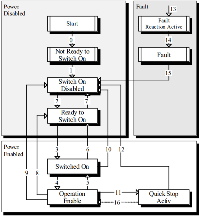
3.2 Control word
| BIT | Content | Description | Remarks |
|---|---|---|---|
| 0 | so | Switch on | Active at 1 |
| 1 | ev | Enable voltage | Fixed 1 |
| 2 | qs | Quick stop | Active at 0 |
| 3 | eo | Enable operation | Active at 1 |
| 4 ~ 6 | oms | Operation mode specific | |
| 7 | fr | Fault reset | Active at 1 |
| 8 | h | Halt | |
| 9 | h | Operation mode specific | |
| 10 | r | Reserved | |
| 15 ~ 11 | r | Manufacturer-defined |
3.3 Status word
| BIT | Name | Description | Remarks |
|---|---|---|---|
| 0 | rtso | Ready | Fixed 1 |
| 1 | so | Switch on | Fixed 1 |
| 2 | oe | Operation enabled | Active at 1 |
| 3 | f | Fault | Active at 1 |
| 4 | ve | Voltage enabled | Fixed 1 |
| 5 | qs | Quick stop | Active at 0 |
| 6 | sod | swd | Fixed 1 |
| 7 | w | Warning | Active at 1 |
| 8 | ms | Manufacturer-defined | |
| 9 | rm | Remote | Fixed 1 |
| 10 | tr | Target reached | |
| 11 | ite | Limit | |
| 12 13 | oms | Operation mode specific | |
| 13 14 | ms | Manufacturer-defined |