Power and Wiring
Back to the getting-started path
This page is the physical layer shared by both routes — Bus servo setup and PWM servo setup: identify the interface first, then wire up, and power on last. Workmanship and parameters always follow that model's documents (if you have already picked a reference model, the "Current reference model" banner at the top of the page is the entry to its tables; if not, find the model in Product Selection first, then open the model page's "Downloads and completeness" section).
Bill of materials
The parts below are shared by both routes; route-specific items are marked in the table. Model-related parameters always follow the documents.
| Item | Key points |
|---|---|
| Power supply | Voltage within the complete model's range; estimate current as "number of servos moving at once × per-servo peak demand" and leave margin; a USB port never carries motor power |
| Harness and terminal wires | Match the servo's interface; reserve length for the layout; wires that are too thin, too long or poorly contacted cause voltage drop and communication errors |
| Debug board or controller | Bus route: a matching USB debug board; PWM route: an MCU PWM output or an RC receiver (see Debug Boards and Adapters) |
| Host software and drivers (bus route) | The serial debug tool UartAssist ("host software" means the debugging software on your PC — open the download page and click "Download") and the debug board's driver |
| Parameter tool (PWM route, optional) | Only programmable models need it, for writing parameters (travel limits and so on); the tools and procedure are in PWM servo setup |
| Optional: multimeter, current-limited supply | Measure voltage and polarity before and after power-up; a current-limited supply works for the first no-load test, but the limit must not be so low that the voltage sags the moment it starts |
For the first power-up connect only one servo; the wiring and the checks are below.
Interface categorisation
Start from the model prefix to determine the family and control interface (see Series and Interfaces), then cross-check by counting the harness wires; this section lists only the common interface types and harnesses, and the actual interface shape, pinout and wire order follow the physical unit and the supplied drawings.
Figure 1 (Interface categorisation · Four harness types): how to identify them and what each harness contains:
- Use the wire count to place the interface in one class; TTL and PWM both have 3 wires, so separate them by model prefix as well (see Series and Interfaces).
- Counting wires only tells you "which class", not "which wire is which" — wire colours and pin order always follow the physical unit and the supplied drawings; never infer them from colours.
- The CAN connector (FU-8830) has 6 pins in two groups: the CAN group's GND, CAN-L and CAN-H carry communication, and supply positive comes from the same connector's Vcc pin (pinout in Get started).
Wiring topology
The two routes wire differently but share one rule: communication and power are supplied separately, and they must share a common ground.
Figure 2 (Bus route · Basic wiring): USB carries communication and powers the debug board itself, but never the servo motors; motor power must come from an external regulated supply, and the debug board's ground and the supply's ground must be connected.
The URT-2 debug board turns Figure 2's abstract chain into hardware: the TYPE-C side connects to a PC (with the serial debug tool — UartAssist in the bill of materials) or an MCU (choose one; see the note in the images), and the other side connects a TTL or RS-485 servo chain by interface type; motor power comes from the terminal block's external supply, with communication and power still on separate paths.
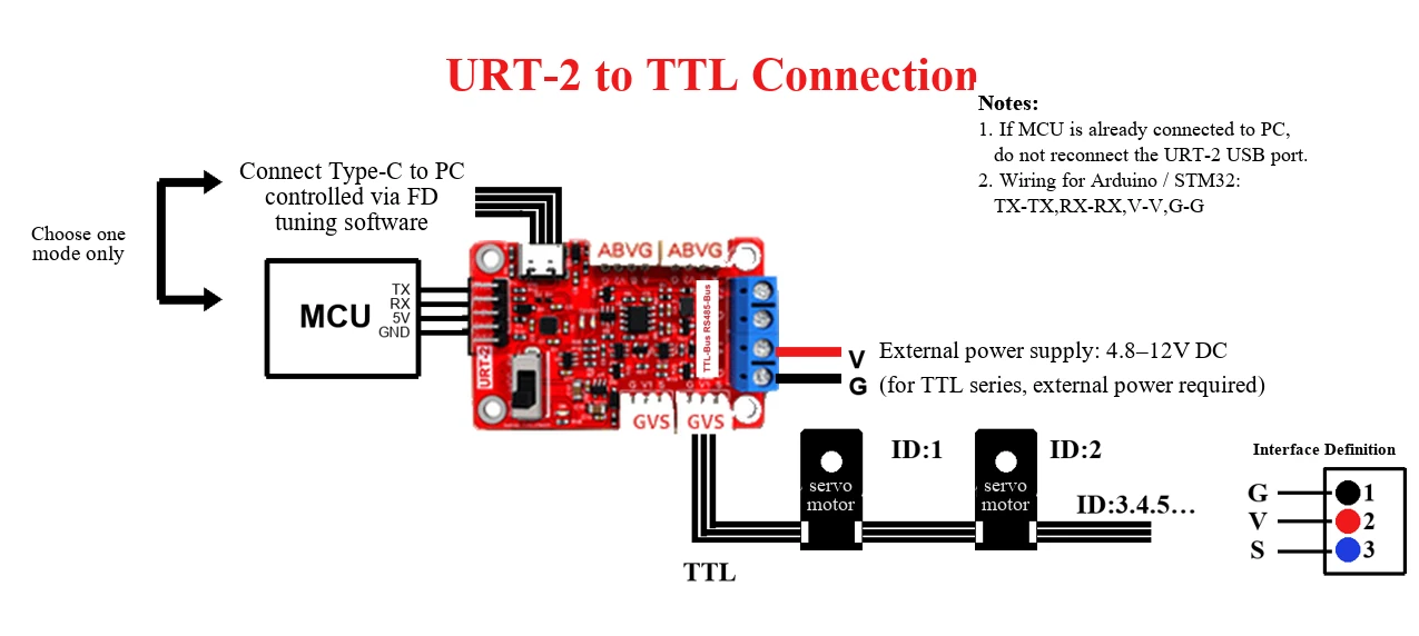
Figure 3 (Bus route · Example): URT-2 to TTL wiring:
- Connect the TYPE-C side to a PC or an MCU (choose one).
- Connect the other side to the TTL servo chain.
- Motor power comes from the external supply terminal.
- If the MCU is 3.3 V, power the debug board from USB instead.
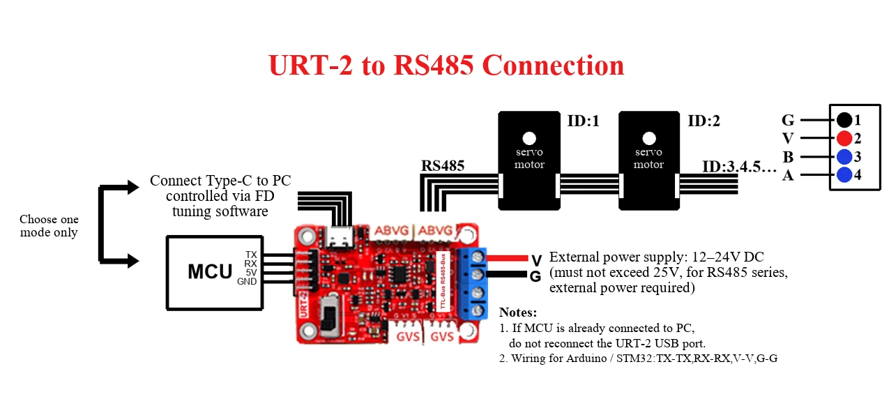
Figure 4 (Bus route · Example): URT-2 to RS-485 wiring:
- Connect the TYPE-C side to a PC or an MCU (choose one).
- Connect the other side to the RS-485 servo chain.
- Motor power comes from the external supply terminal.
- If the MCU is 3.3 V, power the debug board from USB instead.
Figure 5 (PWM route · Basic wiring): the signal comes only from the controller's PWM output (or an RC receiver); power is supplied independently, and the grounds must be common.
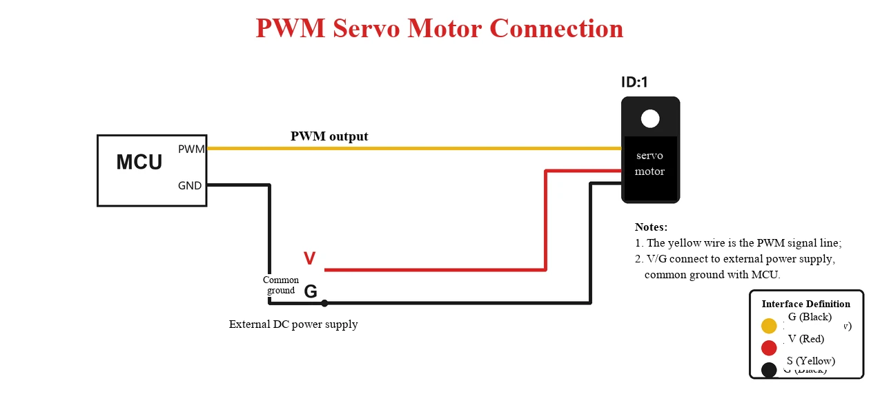
Figure 6 (PWM route · Example): PWM MCU wiring:
- The yellow wire is the PWM signal line — run it from the MCU's PWM output to the servo's signal pin.
- Power V and G come from an external DC supply.
- The supply's G and the MCU's GND must share a common ground (required).
Figure 7 (CAN · Basic wiring): CAN adds a transceiver and two termination resistors on top of the bus — one 120 Ω at each end, with the nodes in the middle of the bus; the drawing shows only the differential pair — for ground and power see the hardware example in Figure 8 below, and FU-8830's pinout is in Get started.
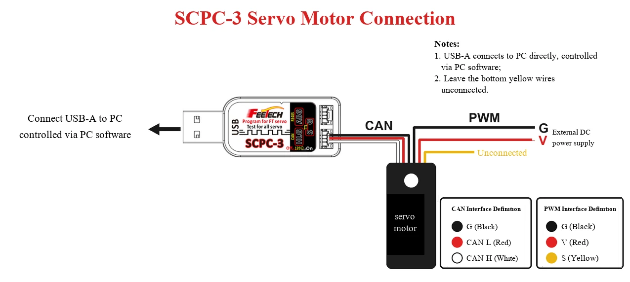
Figure 8 (CAN · Example): CAN wiring with the SCPC-3 (FE-SCPC-C003):
- USB-A goes straight to the PC, controlled by the host software.
- The CAN interface's three wires G, CAN-L and CAN-H go to the servo (matching FU-8830's CAN group).
- Power V comes from an external DC supply and shares its ground with G.
- The servo's bottom-row yellow S wires stay unconnected.
- The board's 120 Ω termination resistor is switched on as the bus requires (see Debug Boards and Adapters).
Supply capacity
Working voltage ranges by family
| Family | Common range across models | Notes |
|---|---|---|
SCS (SC-) |
3.7–8.4 V, mostly 4.8–7.4 V | Entry-level serial bus |
STS (ST-) |
4.8–14 V, commonly 4.8–12 V | Mainstream all-rounder |
SMS (SM-) |
9–25.2 V, mainly 12 V and 24 V | RS-485 |
HLS (HL-) |
4.5–14 V, commonly 9–12.6 V | Constant force |
HD (HD-) |
4–8.4 V | 1 model for now |
FU (FU-) |
6–8.4 V | CAN |
PWM (FT / FB / FS / FR / FI) |
Mostly 3–9 V, plus 12 V and 16–28 V variants | Wide mechanical variety |
Allowed ranges differ between models within one family — the table only shows the distribution; always check the datasheet for your exact model, and when the website's parameter table and the supplied PDF disagree, the model page's marking decides.
- For multi-servo projects, supply in groups, add suitable decoupling near the bus, and keep a reliable common ground.
- When testing with a current-limited supply for the first time, the limit must not be so low that the voltage sags the moment it starts, and do not raise it blindly before verifying.
Bus rules
- IDs on one bus must be unique, and the baud rate must match.
- TTL, RS-485 and CAN each need their own physical interface and must not be cross-connected.
- Avoid long star branches and loose connectors; complex RS-485 networks need termination designed against cable length and speed.
- CAN needs a transceiver — use a USB-to-CAN debug board (e.g. FE-SCPC-C003); node addresses (NODE_ID) must be unique, and the differences are in Bus servo setup.
- Cut the power before unplugging servos or the supply, or changing any wiring.
Pre-power checks
Shared by both routes
| Check | Confirm |
|---|---|
| Model | The full suffix matches the label |
| Voltage | The supply output matches the model's datasheet |
| Polarity | V+, GND and signal/A/B follow the physical unit and the supplied drawings |
| Mechanical | The output shaft can move safely, without pinching or hitting a limit |
| Quantity | Only one servo connected the first time |
Added per route
| Route | Additional checks |
|---|---|
| Bus (TTL / RS-485 / CAN) | The debug board matches the interface type; IDs are unique; the baud rate matches; the CAN node address is confirmed |
| PWM | The MCU's PWM output is off while wiring; period and pulse width are set per the documents; the signal level matches the MCU |
Power up only after both tables check out — that completes the wiring self-check.
Record when done
Record the complete model and suffix, the supply's model and measured output voltage, the interface type and photos of the actual wiring, the item-by-item pre-power check results, and the date. Re-check after changing the supply, the cables or the interface type; do not reuse this record.